Chapter 18 Annotations
Annotations are intended for storing extra information about a model, such as graphics, documentation or versioning, etc. A Modelica tool is free to define and use other annotations, in addition to those defined here, according to section 18.1.
Annotations are optional in the Modelica grammar, and when present, indicated using the annotation keyword, see annotation-clause in the grammar (section A.2.7). The structure of the annotation content is the same as a class modification (class-modification in the grammar). (For replaceable class declarations with a constraining-clause also refer to section 7.3.2.1.) The specification in this document defines the semantic meaning if a tool implements any of these annotations.
18.1 Vendor-Specific Annotations
A vendor may -- anywhere inside an annotation -- add specific, possibly undocumented, annotations which are not intended to be interpreted by other tools. The only requirement is that any tool shall save files with all vendor-specific annotations (and all annotations from this chapter) intact. Two variants of vendor-specific annotations exist; one simple and one hierarchical. Double underscore concatenated with a vendor name as initial characters of the identifier are used to identify vendor-specific annotations.
[Example:
This introduces a new graphical primitive Circle using the hierarchical variant of vendor-specific annotations.
This introduces a new attribute __NameOfVendor_shadow for the Rectangle primitive using the simple variant of vendor-specific annotations.]
18.2 Annotations for Documentation
The Documentation annotation has the following contents, where the info and revisions annotations are described in section 18.2.1, and the figures annotation is described in section 18.2.2:
How the tool interprets the information in Documentation is unspecified.
18.2.1 Class Description and Revision History
Inside the Documentation annotation, the info annotation gives a textual description of the class, and the revisions annotation gives a revision history.
[The revisions documentation may be omitted in printed documentation.]
If the string starts with the tag <html> or <HTML> the entire string is HTML encoded (and is assumed to end with </html> or </HTML> and shall be rendered as HTML even if the end-tags are missing), otherwise the entire string is rendered as is. The HTML encoded content may contain links. For external links, see section 13.5. Links to Modelica classes may be defined with the HTML link command using scheme Modelica (using its lower case form in the URI, see section 13.5), e.g.,
Together with scheme Modelica the (URI) fragment specifiers #diagram, #info, #text, #icon may be used to reference different layers. User-defined fragment specifiers (anchors) may also be used, and they may be renamed when generating HTML (in particular to avoid collisions). Example:
18.2.2 Annotations for Figures
Inside the Documentation annotation, each element of the figures annotation array has the following content:
A Figure is a graphical container that can contain several plots described by Plot annotations:
A Plot can contain several curves, see section 18.2.2.2, that all share a common x and y axis with properties described in section 18.2.2.1.
Both Figure and Plot can have an optional title. When the Figure title is the empty string (the default), the tool must produce a non-empty title based on the figure content. On the other hand, the Plot title has a tool-dependent default, but the default may be the empty string. When the Plot title is the empty string, no title should be shown. The plot title is not to be confused with the plot label which is never empty, see below. Variable replacements, as described in section 18.2.2.4, can be used in the title of Figure and Plot.
The identifier in Figure and Plot is an optional String identifier, and is intended to identify the Figure and Plot for programmatic access. The figures annotation is inherited in the sense that each class has a collection of figures comprised by the contents of the figures annotation in the class itself, as well as the figures annotations from any base classes. A Figure must be uniquely identified by its identifier and a class having it in its collection. This means that a Figure identifier must be unique among all Figure annotations within the same figures annotation as well as among all figures annotations from inherited classes. A Plot identifier on the other hand is only required to be unique among the plots in the the same Figure annotation.
[For Figure, this makes it possible to reference the plot from a tool-specific scripting environment. For Plot, this makes it possible to reference the plot in the figure caption, which becomes useful when the Figure contains more than one Plot.]
Even though a Figure annotation can be shared through inheritance between classes in a class hierarchy, note that each simulated class provides its own data to be displayed in the figure.
Every Plot has an automatically generated label which is required to be shown as soon as at least one Plot in the Figure has an identifier. A tool is free to choose both labeling scheme (such as a, b, …, or i, ii, …), placement in the plot, and styling in the plot itself as well as in other contexts.
When a Figure defines a non-empty group, it is used to organize figures similar to how group is used in the Dialog annotation (see section 18.7). However, leaving group at the default of an empty string does not mean that a group will be created automatically, but that the figure resides outside of any group. The group is both the key used for grouping, and the name of the group for display purposes.
The preferred attribute of Figure indicates whether the figure should be given preference when automatically determining which figures to show, and a class may define any number of preferred figures. For example, a tool might choose to automatically show all preferred figures when the class is simulated.
The caption attribute of Figure can use the restricted form of text markup described in section 18.2.2.5 as well as the variable replacements described in section 18.2.2.4.
18.2.2.1 Axis Properties
Properties may be defined for each Plot axis:
When an axis bound isn’t provided, the tool computes one automatically.
An empty unit means that the axis is unitless, and each expression plotted against it may use its own unit determined by the tool. The tool is responsible for conveying the information about choice of unit for the different variables, for instance by attaching this information to curve legends.
The Modelica tool is responsible for showing that values at the axis tick marks are expressed in unit, so the axis label shall not contain this information.
[When unit is empty, and axis bounds are to be determined automatically, a natural choice of unit could be the variable’s displayUnit. When axis bounds are specified by the user, on the other hand, a tool may choose a unit for the variable such that the range of the variable values (expressed in the chosen unit) fit nicely with the range of the unitless axis.]
If a tool does not recognize the unit, it is recommended to issue a warning and treat the unit as if it was empty, as well as ignore any setting for min and max.
When an axis label isn’t provided, the tool produces a default label. Providing the empty string as axis label means that no label should be shown. Variable replacements, as described in section 18.2.2.4, can be used in the label of Axis The Modelica tool is responsible for showing the unit used for values at the axis tick marks, so the axis label shall not contain the unit.
18.2.2.2 Plot Curves
The actual data to plot is specified in the curves of a Plot:
The mandatory x and y expressions are restricted to be component references referring to a scalar variable or time. It is an error if x or y does not designate a scalar variable. When the unit of an Axis is non-empty, it is an error if the unit of the corresponding Curve expression (i.e., a variable’s unit, or second for time) is incompatible with the axis unit.
When legend isn’t provided, the tool produces a default based on x and/or y. Providing the empty string as legend means that the curve shall be omitted from the plot legend. Variable replacements, as described in section 18.2.2.4, can be used in the legend of Curve
18.2.2.3 Escape sequences
In an attribute inside a figure where the variable replacements of section 18.2.2.4 or the text markup of section 18.2.2.5 can be used, the following use of text markup escape sequences applies. These escape sequences are applied after the application of other markup, and is not applied at all inside some of the other markup, see details for the respective markup.
The percent character ‘%’ shall be encoded %%. The following are all the recognized escape sequences:
| Sequence | Encoded character | Comment |
|---|---|---|
| %% | ‘%’ | Only way to encode character. |
| %] | ‘]’ | Prevents termination of markup delimited by []. |
[With the percent character being encoded as %%, the behavior of % appearing in any other way than the escape sequences above, for variable replacement (section 18.2.2.4), or for the text markup (section 18.2.2.5) is undefined, and thus possible to define in the future without breaking backward compatibility.]
18.2.2.4 Variable Replacements
In the places listed in table 18.1 where text for display is defined, the final value of a result variable can be embedded by referring to the variable as %{inertia1.w}. This is similar to the Text graphical primitive in section 18.6.5.5.
| Attribute | Annotation |
|---|---|
| title | Figure and Plot |
| caption | Figure |
| legend | Curve |
| label | Axis |
In %{}, text markup escape sequences don’t apply inside the , which has the form of component-reference in the grammar (section A.2.7). This means that a complete component-reference shall be scanned before looking for the terminating closing brace.
[Example: The variable replacement %{’%%’} references the variable ’%%’, not the variable ’%’.]
[Example: The variable replacement %{foo . ’}bar{’} makes a valid reference to the variable foo.’}bar{’.]
Note that expansion to the final value means that expansion is not restricted to parameters and constants, so that values to be shown in a caption can be determined during simulation.
[By design, neither %class nor %name is supported in this context, as this information is expected to already be easily accessible (when applicable) in tool-specific ways. (Titles making use of %class or %name would then only lead to ugly duplication of this information.)]
18.2.2.5 Text Markup in Captions
In addition to variable replacements, a very restricted form of text markup is used for the caption. Note that the text markup escape sequences described in section 18.2.2.3 generally apply inside caption, with one exception given below for links.
Links take the form %[](), where the [] part is optional, and text markup escape sequences don’t apply inside the . The can be in either of the following forms, where the interpretation is given by the first matching form:
-
•
A variable:, where is a component reference in the form of component-reference in the grammar, such as inertia1.w.
-
•
A plot:, where is the identifier of a Plot in the current Figure.
-
•
A URI. Well established schemes such as https://github.com/modelica or modelica://Modelica, as well as lesser known schemes may be used. (A tool that has no special recognition of a scheme can try sending the URI to the operating system for interpretation.)
When [] is omitted, a Modelica tool is free to derive a default based on the .
[Note that for the character ‘]’ to appear in , it needs to be encoded as the escape sequence %], or it would be interpreted as the terminating delimiter of the [].
Similarly, the closing parenthesis ‘)’ must be handled with care in in order to not be interpreted as the terminating delimiter of the ().
-
•
For a variable:, no special treatment is needed, as the component reference syntax of the allows parentheses to appear without risk of misinterpretation inside a quoted identifier. For example, %(variable:’try)me!’) has a parenthesis in ’try)me!’ that must not be mistaken for the end of the ().
-
•
For a plot:, there is currently no way to reference a plot with ‘)’ in its identifier.
-
•
For a URI, a closing parenthesis must be URL encoded in order to not be interpreted as the end of the (). For example, the URL in %(http://example.org/(tryme)) is just http://example.org/(tryme, and the entire link is followed by a stray closing parenthesis. To make it work, one has to use URL encoding: %(http://example.org/%28tryme%29) (using URL encoding of the opening parenthesis just for symmetry, and note that the % of the percent-encoded sequences are not subject to text markup escape sequences).
]
The styling of the link text, as well as the link action, is left for each Modelica tool to decide.
[For example, %(inertia1.w) could be displayed as the text inertia1.w formatted with upright monospaced font, and have a pop-up menu attached with menu items for plotting the variable, setting its start value, or investigating the equation system from which it is solved. On the other hand, %[angular velocity](inertia1.w) could be formatted in the same style as the surrounding text, except some non-intrusive visual clue about it being linked.]
[Note that is currently not allowed to be a URI reference, i.e., a URI or a relative reference such as #foo. This is due to to the current inability to define a base URI referencing the current figure. Once this becomes possible, the URI form of may be changed into a URI reference.]
A sequence of one or more newlines (encoded either literally or using the \n escape sequence) means a paragraph break. (A line break within a paragraph is not supported, and any paragraph break before the first paragraph or after the last paragraph has no impact.)
Vendor-specific markup takes the form %__()__()[], where . The consists of only digits and letters, and shall only convey the name of the vendor defining the meaning of the associated . Text markup escape sequences don’t apply inside the , implying that it cannot contain the closing parenthesis, ‘)’. A tool which does not understand any of the vendor-specific meanings shall only display the mandatory , but the may also be used together with the vendor-specific .
[Example: One application of vendor-specific markup is to prototype a feature that can later be turned into standardized markup. For example, say that the tool AVendor wants to generalize the variable replacements such that the duration of a simulation can be substituted into a caption. During the development, this could be represented as the vendor-specific markup %__AVendor(?duration)[10 s], if the simulation has a duration of 10 seconds at the time of writing the caption. When AVendor renders this, it ignores the text 10 s and just displays the actual duration instead. Later, if this would become supported by standard markup, it might take the form of something like %{experiment:duration} instead (note that experiment:duration is not in the form of a component reference, avoiding conflict with current use of variable replacements).
In a similar way, vendor-specific markup can be used to prototype a link for future inclusion in the link markup (either by extending the meaning of Modelica URIs, or by introducing another pseudo-scheme similar to variable:). This is an example where the vendor-specific markup could make use of the (for link text) together with the vendor-specific (describing the actual link).]
18.3 Annotations for Code Generation
The annotations listed below, appearing directly inside annotation(), can influence the code generation.
| Annotation | Description | Details |
|---|---|---|
| Evaluate | Use parameter value for symbolic processing | Annotation 18.1 |
| HideResult | Don’t show component’s simulator result | Annotation 18.2 |
| Inline | Inline function | Annotation 18.3 |
| LateInline | Inline after all symbolic transformations | Annotation 18.4 |
| InlineAfterIndexReduction | Inline after index reduction | Annotation 18.5 |
| GenerateEvents | Generate events for zero crossings in function | Annotation 18.6 |
| smoothOrder | Function smoothness guarantee | Annotation 18.7 |
Annotation 18.1 Evaluate
-
The annotation Evaluate can occur in the component declaration, its type declaration, or a base-class of the type-declaration. In the case of multiple conflicting annotations it is handled similarly to modifiers (e.g., an Evaluate annotation on the component declaration takes precedence). In the case of hierarchical components it is applied to all components, overriding any Evaluate-setting for specific components. The annotation Evaluate only has effect for a component declared with the prefix parameter.
If Evaluate = true, the model developer proposes to utilize the value for the symbolic processing. In that case, it is not possible to change the parameter value after symbolic pre-processing.
If Evaluate = false, the model developer proposes to not utilize the value of the corresponding parameter for the symbolic processing.
[Evaluate is for example used for axis of rotation parameters in the Modelica.Mechanics.MultiBody library in order to improve the efficiency of the generated code.]
Annotation 18.2 HideResult
-
HideResult = true defines that the model developer proposes to not show the simulator results of the corresponding component.
HideResult = false defines that the developer proposes to show the corresponding component.
[For example, a tool is not expected to provide means to plot a variable with HideResult = true. If a variable is declared in a protected section, a tool might not include it in a simulation result. By setting HideResult = false, the modeler would like to have the variable in the simulation result, even if in the protected section.
HideResult is for example used in the connectors of the Modelica.StateGraph library to not show variables to the modeler that are of no interest to him and would confuse him.]
Annotation 18.3 Inline
-
Has only an effect within a function declaration.
If Inline = true, the model developer proposes to inline the function. This means, that the body of the function is included at all places where the function is called.
If Inline = true, the model developer proposes to not inline the function.
[Inline = true is for example used in Modelica.Mechanics.MultiBody.Frames and in functions of Modelica.Media to have no overhead for function calls such as resolving a vector in a different coordinate system and at the same time the function can be analytically differentiated, e.g., for index reduction needed for mechanical systems.]
Annotation 18.4 LateInline
-
Has only an effect within a function declaration.
If LateInline = true, the model developer proposes to inline the function after all symbolic transformations have been performed.
[Late inlining is especially useful for differentiation and inversion of functions; for efficiency reasons it is then useful to replace all function calls with identical input arguments by one function call, before the inlining.]
If LateInline = false, the model developer proposes to not inline the function after symbolic transformations have been performed.
Inline = true, LateInline = false is identical to Inline = true.
Inline = true, LateInline = true is identical to LateInline = true.
Inline = false, LateInline = true is identical to LateInline = true.
[This annotation is for example used in Modelica.Media.Water.IF97_Utilities.T_props_ph to provide in combination with common subexpression elimination the automatic caching of function calls. Furthermore, it is used in order that a tool is able to propagate specific enthalpy over connectors in the Modelica.Fluid library.]
Annotation 18.5 InlineAfterIndexReduction
-
Has only an effect within a function declaration.
If true, the model developer proposes to inline the function after the function is differentiated for index reduction, and before any other symbolic transformations are performed. This annotation cannot be combined with annotations Inline and LateInline.
Annotation 18.6 GenerateEvents
-
Has only an effect within a function declaration
If GenerateEvents = true, the model developer proposes that crossing functions in the function should generate events (one possibility of doing this is to inline the function and generate events for the inlined function).
[This annotation is for example used in Modelica.Media.Water.IF97_Utilities.phase_dT to indicate that the output should generate an event when it changes.]
Annotation 18.7 smoothOrder
-
This annotation has only an effect within a function declaration.
smoothOrder defines the number of differentiations of the function, in order that all of the differentiated outputs are continuous provided all input arguments and their derivatives up to order smoothOrder are continuous.
[This means that the function is at least CsmoothOrder. smoothOrder = 1 means that the function can be differentiated at least once in order that all output arguments are still continuous, provided the input arguments are continuous. If a tool needs the derivative of a function, e.g. for index reduction or to compute an analytic Jacobian, the function can be differentiated analytically at least smoothOrder times.]
The optional argument normallyConstant of smoothOrder defines that the function argument IDENT is usually constant.
[A tool might check whether the actual argument to IDENT is a parameter expression at the place where the function is called. If this is the case, the derivative of the function might be constructed under the assumption that the corresponding argument is constant, to enhance efficiency. Typically, a tool would generate at most two different derivative functions of a function: One, under the assumption that all normallyConstant arguments are actually constant. And one, under the assumption that all input arguments are time varying. Based on the actual arguments of the function call either of the two derivative functions is used.
This annotation is used by many functions of the Modelica.Fluid library, such as Modelica.Fluid.Dissipation.PressureLoss.StraightPipe.dp_laminar_DP, since geometric arguments to these functions are usually constant.]
18.4 Annotations for Simulations
These annotations define how models can be checked, translated, and simulated.
18.4.1 Annotations for Simulation Experiments
The experiment annotation defines the default start time (StartTime) in [s], the default stop time (StopTime) in [s], the suitable time resolution for the result grid (Interval) in [s], and the default relative integration tolerance (Tolerance) for simulation experiments to be carried out with the model or block at hand. If StartTime is not specified it is assumed to be 0.0.
18.4.2 Annotation for Test Cases
If shouldPass is false it indicates that the translation or the simulation of the model should fail. If a tools checks a package where classes have shouldPass = false they should not generate errors, and checking may even be skipped. On the other hand, models with shouldPass = false may be useful for creation of negative tests in tool-specific ways. Similarly as a class with obsolete-annotation, a class with TestCase annotation (regardless of the value of shouldPass) shall not be used in other models, unless those models also have a TestCase annotation.
[The intent of the test-case can be included in the documentation of the class. This annotation can both be used for models intended as test-cases for implementations, and for models explaining detectable errors.]
18.5 Annotation for single use of class
For state machines it is useful to have single instances of local classes. This can be done using:
The annotation singleInstance in a class indicates that there should only be one component instance of the class, and it should be in the same scope as the class is defined. The intent is to remove the class when the component is removed and to prevent duplication of the component.
18.6 Annotations for Graphical Objects
A graphical representation of a class consists of two abstraction layers, icon layer and diagram layer showing graphical objects, component icons, connectors and connection lines. The icon representation typically visualizes the component by hiding hierarchical details. The hierarchical decomposition is described in the diagram layer showing icons of subcomponents and connections between these.
Graphical annotations described in this chapter ties into the Modelica grammar as follows.
Layer descriptions (start of syntactic description):
[Example:
]
The graphics is specified as an ordered sequence of graphical primitives, which are described below. First base-class contents is drawn according to the order of the extends-clauses, and then graphical primitives are drawn according to the order such that later objects can cover earlier ones.
[Note that the ordered sequence is syntactically a valid Modelica annotation, although there is no mechanism for defining an array of heterogeneous objects in Modelica.]
These Icon, Diagram, and Documentation annotations are only allowed directly in classes (e.g. not on components or connections). The allowed annotations for a short class definition is the union of the allowed annotations in classes and on extends-clauses.
18.6.1 Common Definitions
The following common definitions are used to define graphical annotations in the later sections.
The interpretation of unit is with respect to printer output in natural size (not zoomed).
All graphical entities have a visible attribute which indicates if the entity should be shown.
The origin attribute specifies the origin of the graphical item in the coordinate system of the layer in which it is defined. The origin is used to define the geometric information of the item and for all transformations applied to the item. All geometric information is given relative the origin attribute, which by default is {0, 0}.
The rotation attribute specifies the rotation of the graphical item counter-clockwise around the point defined by the origin attribute.
18.6.1.1 Coordinate Systems
Each of the layers has its own coordinate system. A coordinate system is defined by the coordinates of two points, the left (x1) lower (y1) corner and the right (x2) upper (y2) corner, where the coordinates of the first point shall be less than the coordinates of the second point.
The attribute preserveAspectRatio specifies a hint for the shape of components of the class, but does not actually influence the rendering of the component. If preserveAspectRatio is true, changing the extent of components should preserve the current aspect ratio of the coordinate system of the class.
The attribute initialScale specifies the default component size as initialScale times the size of the coordinate system of the class. An application may use a different default value of initialScale.
The attribute grid specifies the spacing between grid points which can be used by tools for alignment of points in the coordinate system, e.g. “snap-to-grid”. Its use and default value is tool-dependent.
[Example: A coordinate system for an icon could for example be defined as:
i.e. a coordinate system with width 20 units and height 20 units.]
The coordinate systems for the icon and diagram layers are by default defined as follows; where the array of GraphicsItem represents an ordered list of graphical primitives.
The coordinate system (including preserveAspectRatio) of a class is defined by the following priority:
-
1.
The coordinate system annotation given in the class (if specified).
-
2.
The coordinate systems of the first base-class where the extent on the extends-clause specifies a null-region (if any). Note that null-region is the default for base-classes, see section 18.6.3.
-
3.
The default coordinate system CoordinateSystem(extent = {{-100, -100}, {100, 100}}).
18.6.1.2 Graphical Properties
Properties of graphical objects and connection lines are described using the following attribute types.
The LinePattern attribute Solid indicates a normal line, None an invisible line, and the other attributes various forms of dashed/dotted lines.
The FillPattern attributes Horizontal, Vertical, Cross, Forward, Backward and CrossDiag specify fill patterns drawn with the line color over the fill color.
The attributes HorizontalCylinder, VerticalCylinder and Sphere specify gradients that represent a horizontal cylinder, a vertical cylinder and a sphere, respectively. The gradient goes from line color to fill color.
The border pattern attributes Raised, Sunken and Engraved represent frames which are rendered in a tool-dependent way — inside the extent of the filled shape.
The smooth attribute specifies that a line can be drawn as straight line segments (None) or using a spline (Bezier), where the line’s points specify control points of a quadratic Bezier curve, see figure 18.1.
For lines with only two points, the smooth attribute has no effect.
For lines with three or more points (, , …, ), the middle point of each line segment (, , …, ) becomes the starting point and ending points of each quadratic Bezier curve. For each quadratic Bezier curve, the common point of the two line segment becomes the control point. For instance, point becomes the control point for the Bezier curve starting at and ending at . A straight line is drawn between the starting point of the line and the starting point of the first quadratic Bezier curve, as well as between the ending point of the line and the ending point of the last quadratic Bezier curve.
In the illustration above, the square points (, , , and ) represent the points that define the line, and the circle points (, , and ) are the calculated middle points of each line segment. Points , , and define the first quadratic Bezier curve, and the points , , and define the second quadratic Bezier curve. Finally a straight line is drawn between points and as well as between and .
The values of the EllipseClosure enumeration specify if and how the endpoints of an elliptical arc are to be joined (see section 18.6.5.4).
Filled shapes have the following attributes for the border and interior.
The extent/points of the filled shape describe the theoretical zero-thickness filled shape, and the actual rendered border is then half inside and half outside the extent.
18.6.2 Component Instance
A component instance can be placed within a diagram or icon layer. It has an annotation with a Placement modifier to describe the placement. Placements are defined in term of coordinate systems transformations:
The origin attribute defines the position of the component in the coordinate system of the enclosing class. The extent defines the position, size and flipping of the component, relative to the origin attribute. The extent is defined relative to the origin attribute of the component instance. Given an extent {{, }, {, }}, defines horizontal flipping and defines vertical flipping around the center of the object.
The rotation attribute specifies rotation of the extent around the point defined by the origin attribute.
The graphical operations are applied in the order: scaling, flipping and rotation.
If no iconTransformation is given the transformation is also used for placement in the icon layer. If no iconVisible is given for a public connector the visible is also used for visibility in the icon layer.
[A connector can be shown in both an icon layer and a diagram layer of a class. Since the coordinate systems typically are different, placement information needs to be given using two different coordinate systems. More flexibility than just using scaling and translation is needed since the abstraction views might need different visual placement of the connectors. The attribute transformation gives the placement in the diagram layer and iconTransformation gives the placement in the icon layer. When a connector is shown in a diagram layer, its diagram layer is shown to facilitate opening up a hierarchical connector to allow connections to its internal subconnectors.]
For connectors, the icon layer is used to represent a connector when it is shown in the icon layer of the enclosing model. The diagram layer of the connector is used to represent it when shown in the diagram layer of the enclosing model. Protected connectors are only shown in the diagram layer. Public connectors are shown in both the diagram layer and the icon layer. Non-connector components are only shown in the diagram layer.
18.6.3 Extends clause
Each extends-clause (and short-class-definition, as stated in section 18.6) may have layer specific annotations which describe the rendering of the base class’ icon and diagram layers in the derived class.
All graphical objects are by default inherited from a base class. If the primitivesVisible attribute is false, components and connections are visible but graphical primitives are not.
-
•
If the extent of the extends-clause defines a null region (the default), the base class contents is mapped to the same coordinates in the derived class, and the coordinate system (including preserveAspectRatio) can be inherited as described in section 18.6.1.1.
-
•
If the extent of the extends-clause defines a non-null region, the base class coordinate system is mapped to the region specified by the attribute extent, if preserveAspectRatio is true for the base class the mapping shall preserve the aspect ratio. The base class coordinate system (and preserveAspectRatio) is not inherited.
[Example:
In this example the diagram of A contains the graphical primitives from A and B (but not from C since they were hidden in B) – the ones from B are rescaled, and the icon of A contains the graphical primitives from A (but neither from B nor from C).]
18.6.4 Connections
A connection is specified with an annotation containing a Line primitive and optionally a Text primitive, as specified below.
[Example:
]
The optional Text primitive defines a text that will be written on the connection line. It has the following definition (it is not equal to the Text primitive as part of graphics – the differences are marked as bold lines):
The index is one of the points of Line (numbered 1, 2, 3, … where negative numbers count from the end, thus -1 indicate the last one). The string may use the special symbols "%first" and "%second" to indicate the connectors in the connect-equation.
The extent and rotation are relative to the origin (default {0, 0}) and the origin is relative to the point on the Line.
The textColor attribute defines the color of the text. The text is drawn with transparent background and no border around the text (and without outline). The contents inherited from FilledShape is deprecated, but kept for compatibility reasons. The default value for horizontalAlignment is deprecated. Having a zero size for the extent is deprecated and is handled as if upper part is moved up an appropriate amount.
[Example:
Draws a connection line and adds the text axisControlBus1 ending at and 4 vertical units of space for the text. Using a height of zero, such as extent = [-6, 3; -6, 3] is deprecated, but gives similar result.]
18.6.5 Graphical primitives
This section describes the graphical primitives that can be used to define the graphical objects in an annotation.
18.6.5.1 Line
A line is specified as follows:
Note that the Line primitive is also used to specify the graphical representation of a connection.
For arrows:
-
•
The arrow is drawn with an aspect ratio of 1/3 for each arrow half, i.e., if the arrow-head is 3 mm long an arrow with Half will extend 1 mm from the mid-line and with Open or Filled extend 1 mm to each side, in total making the base 2 mm wide.
-
•
The arrowSize gives the width of the arrow (including the imagined other half for Half) so that lineThickness = 10 and arrowSize = 10 will touch at the outer parts.
-
•
All arrow variants overlap for overlapping lines.
-
•
The lines for the Open and Half variants are drawn with lineThickness.
18.6.5.2 Polygon
A polygon is specified as follows:
The polygon is automatically closed, if the first and the last points are not identical.
18.6.5.3 Rectangle
A rectangle is specified as follows:
The extent attribute specifies the bounding box of the rectangle. If the radius attribute is specified, the rectangle is drawn with rounded corners of the given radius.
18.6.5.4 Ellipse
An ellipse is specified as follows:
The extent attribute specifies the bounding box of the ellipse.
Partial ellipses can be drawn using the startAngle and endAngle attributes. These specify the endpoints of the arc prior to the stretch and rotate operations. The arc is drawn counter-clockwise from startAngle to endAngle, where startAngle and endAngle are defined counter-clockwise from 3 o’clock (the positive x-axis).
The closure attribute specifies whether the endpoints specified by startAngle and endAngle are to be joined by lines to the center of the extent (closure = EllipseClosure.Radial), joined by a single straight line between the end points (closure = EllipseClosure.Chord), or left unconnected (closure = EllipseClosure.None). In the latter case, the ellipse is treated as an open curve instead of a closed shape, and the fillPattern and fillColor are not applied (if present, they are ignored).
The default closure is EllipseClosure.Chord when startAngle is 0 and endAngle is 360, or EllipseClosure.Radial otherwise.
[The default for a closed ellipse is not EllipseClosure.None, since that would result in fillColor and fillPattern being ignored, making it impossible to draw a filled ellipse. EllipseClosure.Chord is equivalent in this case, since the chord will be of zero length.]
18.6.5.5 Text
A text string is specified as follows:
The textColor attribute defines the color of the text. The text is drawn with transparent background and no border around the text (and without outline). The contents inherited from FilledShape is deprecated, but kept for compatibility reasons.
There are a number of common macros that can be used in the text, and they should be replaced when displaying the text as follows (in order such that the earliest ones have precedence, and using the longest sequence of identifier characters – alphanumeric and underscore):
-
•
%% replaced by %
-
•
%name replaced by the name of the component (i.e., the identifier for it in the enclosing class).
-
•
%class replaced by the name of the class (only the last part of the hierarchical name).
-
•
%par and %{par} replaced by the value of the parameter par. If the value is numeric, tools shall display the value with displayUnit, formatted according to bipm-specification. E.g., for
parameter Real t(unit = "s", displayUnit = "ms") = 0.1tools shall display 100 ms. The intent is that the text is easily readable, thus if par is of an enumeration type, replace %par by the item name, not by the full name.
[Example: If par = "Modelica.Blocks.Types.Enumeration.Periodic", then %par should be displayed as Periodic.]
The form %{par} allows component-references and is required for quoted identifiers, and can be directly followed by a letter. Thus %{w}x%{h} gives the value of w directly followed by x and the value of h, while %wxh gives the value of the parameter wxh. If the parameter does not exist it is an error.
The style attribute fontSize specifies the font size. If the fontSize attribute is 0 the text is scaled to fit its extent. Otherwise, the size specifies the absolute size. The text is vertically centered in the extent.
If the extent specifies a box with zero width and positive height the height is used as height for the text (unless fontSize attribute is non-zero – which specifies the absolute size), and the text is not truncated (the horizontalAlignment is still used in this case).
[A zero-width extent is convenient for handling texts where the width is unknown.]
If the string fontName is empty, the tool may choose a font. The font names "serif", "sans-serif", and "monospace" shall be recognized. If possible the correct font should be used – otherwise a reasonable match, or treat as if fontName was empty.
The style attribute textStyle specifies variations of the font.
18.6.5.6 Bitmap
A bitmap image is specified as follows:
The Bitmap primitive renders a graphical bitmap image. The data of the image can either be stored on an external file or in the annotation itself. The image is scaled to fit the extent. Given an extent {{, }, {, }}, defines horizontal flipping and defines vertical flipping around the center of the object.
The graphical operations are applied in the order: scaling, flipping and rotation.
When the attribute fileName is specified, the string refers to an external file containing image data. The mapping from the string to the file is specified for some URIs in section 13.5. The supported file formats include PNG, BMP, JPEG, and SVG.
When the attribute imageSource is specified, the string contains the image data, and the image format is determined based on the contents. The image is represented as a Base64 encoding of the image file format (see RFC 4648, http://tools.ietf.org/html/rfc4648).
The image is uniformly scaled (preserving the aspect ratio) so it exactly fits within the extent (touching the extent along one axis). The center of the image is positioned at the center of the extent.
18.6.6 Variable Graphics and Schematic Animation
Any value (coordinates, color, text, etc.) in graphical annotations can be dependent on class variables using the DynamicSelect expression. DynamicSelect has the syntax of a function call with two arguments, where the first argument specifies the value of the editing state and the second argument the value of the non-editing state. The first argument must be a literal expression. The second argument may contain references to variables to enable a dynamic behavior.
[Example: The level of a tank could be animated by a rectangle expanding in vertical direction and its color depending on a variable overflow:
]
18.6.7 User input
It is possible to interactively modify variables during a simulation. The variables may either be parameters, discrete-time variables or states. New numeric values can be given, a mouse click can change a Boolean variable or a mouse movement can change a Real variable. Input fields may be associated with a GraphicItem or a component as an array named interaction. The interaction array may occur as an attribute of a graphic primitive, an attribute of a component annotation or as an attribute of the layer annotation of a class.
18.6.7.1 Mouse input
A Boolean variable can be changed when the cursor is held over a graphical item or component and the selection button is pressed if the interaction annotation contains OnMouseDownSetBoolean:
[Example: A button can be represented by a rectangle changing color depending on a Boolean variable on and toggles the variable when the rectangle is clicked on:
]
In a similar way, a variable can be changed when the mouse button is released:
Note that several interaction objects can be associated with the same graphical item or component.
The OnMouseMoveXSetReal interaction object sets the variable to the position of the cursor in X direction in the local coordinate system mapped to the interval defined by the minValue and maxValue attributes.
The OnMouseMoveYSetReal interaction object works in a corresponding way as the OnMouseMoveXSetReal object but in the Y direction.
18.6.7.2 Edit input
The OnMouseDownEditInteger interaction object presents an input field when the graphical item or component is clicked on. The field shows the actual value of the variable and allows changing the value. If a too small or too large value according to the min and max parameter values of the variable is given, the input is rejected.
The OnMouseDownEditReal interaction object presents an input field when the graphical item or component is clicked on. The field shows the actual value of the variable and allows changing the value. If a too small or too large value according to the min and max parameter values of the variable is given, the input is rejected.
The OnMouseDownEditString interaction object presents an input field when the graphical item or component is clicked on. The field shows the actual value of the variable and allows changing the value.
18.7 Annotations for the Graphical User Interface
This section describes the annotations that are used to define properties of the graphical user interface.
The preferredView annotation defines the default view when selecting the class. info means info layer, i.e., the documentation of the class, diagram means diagram layer and text means the Modelica text layer.
Only allowed as class annotation on any kind of class and implies that this class and all classes within it are treated as having the annotation preferredView = "info". If the annotation preferredView is explicitly set for a class, it has precedence over a DocumentationClass annotation.
[A tool may display such classes in special ways. For example, the description texts of the classes might be displayed instead of the class names, and if no icon is defined, a special information default icon may be displayed in the package browser.]
When creating a component of the given class, the recommended component name is name.
When creating a component, it is recommended to generate a declaration of the form
The following prefixes may be included in the string prefixes: inner, outer, replaceable, constant, parameter, discrete.
[In combination with defaultComponentName it can be used to make it easy for users to create inner components matching the outer declarations; see also example below. If the prefixes contain inner or outer and the default name cannot be used (e.g., since it is already in use) it is recommended to give a diagnostic.]
When an outer component of the class does not have a corresponding inner component, the literal string message may be used as part of a diagnostic message (together with appropriate context), see section 5.4.
[Example:
When an instance of model World is dragged in to the diagram layer, the following declaration is generated:
]
A simple type or component of a simple type may have:
If false, then the variable defines a relative quantity, and if true an absolute quantity.
[When converting between units (in the user-interface for plotting and entering parameters), the offset must be ignored for a variable defined with annotation absoluteValue = false. This annotation is used in the Modelica Standard Library, for example in Modelica.Units.SI for the type definition TemperatureDifference.]
A model or block definition may contain:
If true, it is stated that a default connection will result in a structurally inconsistent model or block11 1 For the precise definition of structurally inconsistent, see Pantelides (1988).. A ”default connection” is constructed by instantiating the respective model or block and for every input u providing an equation 0 = f(u), and for every (potential, flow) pair of the form (v, i), providing an equation of the form 0 = f(v, i).
[It is useful to check all models/blocks of a Modelica package in a simple way. One check is to default connect every model/block and to check whether the resulting class is structurally consistent (which is a stronger requirement than being balanced). It is rarely needed; but is for example used in Modelica.Blocks.Math.InverseBlockConstraints, in order to prevent a wrong error message. Additionally, when a user defined model is structurally inconsistent, a tool should try to pinpoint in which class the error is present. This annotation avoids then to show a wrong error message.]
A class may have the following annotation:
It indicates that the class ideally should not be used anymore and gives a message indicating the recommended action. This annotation is not inherited, the assumption is that if a class uses an obsolete class (as a base-class or as the class of one of the components) that shall be updated – ideally without impacting users of the class. If that is not possible the current class can have also have an obsolete annotation.
A component declaration may have the following annotation:
When the variable to which this annotation is attached in the declaration cannot be computed due to the structure of the equations, the string "message" can be used as a diagnostic message.
[When using BLT partitioning, this means if a variable a or one of its aliases b = a or b = -a cannot be assigned, the message is displayed. This annotation is used to provide library specific error messages.]
[Example:
]
A component declaration or a short replaceable class definition may have the following annotation:
For a short replaceable class definition only the fields tab, group, enable and groupImage are allowed.
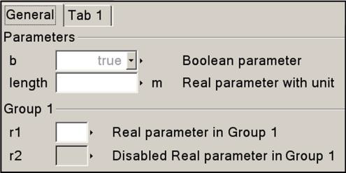
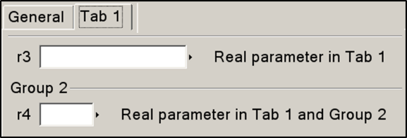
The annotations tab and group define the placement of the component or of variables in a dialog with optional tab and group specification, where the empty string (default) means tool-specific group. The idea is that a tool may as default place parameters in the group “Parameters” in the tab “General”, but add e.g., variables with showStartAttribute=true to another group. If enable = false, the input field may be disabled and no input can be given. If showStartAttribute = true the dialog should allow the user to set the start-value and the fixed attribute for the variable instead of the value of the variable.
[The showStartAttribute = true is primarily intended for non-parameter values and avoids introducing a separate parameter for the start-value of the variable.]
The order of parameters within each group and the order of the groups and tabs are according to the declaration order, where inherited elements are added at the place of the extends.
If colorSelector = true, it indicates that an rgb-value selector can be presented for a vector of three elements and generate values 0..255 (the annotation should be useable both for vectors of Integer and Real).
The annotation groupImage references an image using an URI (see section 13.5), and the image is intended to be shown together with the parameter-group (only one image per group is supported). Disabling the input field will not disable the image.
The background of the groupImage and any image used in HTML-documentation is recommended to be transparent (intended to be a light color) or white.
The value of the connectorSizing annotation must be a literal false or true value. If connectorSizing = false, this annotation has no effect. If connectorSizing = true, the corresponding variable must be declared with the parameter prefix, must be a subtype of a scalar Integer and must have a literal default value of zero.
[The reason why connectorSizing must be given a literal value is that if the value is an expression, the connectorSizing functionality is conditional and this will then lead easily to wrong models.
The default value of the variable must be zero since this annotation is designed for a parameter that is used as vector dimension, and the dimension of the vector should be zero when the component is dragged or redeclared. Furthermore, when a tool does not support the connectorSizing annotation, dragging will still result in a correct model.]
If connectorSizing = true, a tool may set the parameter value in a modifier automatically, if used as dimension size of a vector of connectors.
[The connectorSizing annotation is used in cases where connections to a vector of connectors shall be made and a new connection requires to resize the vector and to connect to the new index (unary connections). The annotation allows a tool to perform these two actions in many cases automatically. This is, e.g., very useful for state machines and for certain components of fluid libraries.]
Annotation Dialog is defined as:
A parameter dialog is a sequence of tabs with a sequence of groups inside them.
A Selector displays a file dialog to select a file. Setting filter only shows files that fulfill the given pattern defined by text1 (*.ext1);;text2 (*.ext2) to show only files with file extension ext1 or ext2 and displaying a description text text1 and text2, respectively. Parameter caption is the text displayed in the dialog menu. Parameter loadSelector is used to select an existing file for reading, whereas parameter saveSelector is used to define a file for writing.
[Example:
When clicking on an instance of model DialogDemo, a menu pops up that may have the following layout (other layouts are also possible, this is vendor specific). Note, parameter nInports is not present in the menu since it has the connectorSizing annotation and therefore it should not be modified by the user (an alternative is to show parameter nInports in the menu but with disabled input field):
]
[The following part is non-normative text and describes a useful way to handle the connectorSizing annotation in a tool (still a tool may use another strategy and/or may handle other cases than described below). The recommended rules are clarified at hand of the following example which represents a connector and a model from the Modelica.StateGraph library:
If the parameter is used as dimension size of a vector of connectors, it is automatically updated according to the following rules:
-
1.
If a new connection line is drawn between one outside and one inside vector of connectors both dimensioned with (connectorSizing) parameters, a connection between the two vectors is performed and the (connectorSizing) parameter is propagated from connector to component. Other types of outside connections do not lead to an automatic update of a (connectorSizing) parameter. Example: Assume there is a connector inPorts and a component step1:
parameter Integer nIn=0 annotation(Dialog(connectorSizing=true));StepIn inPorts[nIn];Step step1(nIn=0);Drawing a connection line between connectors inPorts and step1.inPorts results in:
parameter Integer nIn=0 annotation(Dialog(connectorSizing=true));StepIn inPorts[nIn];Step step1(nIn=nIn); // nIn=0 changed to nIn=nInequationconnect(inPorts, step1.inPorts); // new connect equation -
2.
If a connection line is deleted between one outside and one inside vector of connectors both dimensioned with (connectorSizing) parameters, the connect equation is removed and the (connectorSizing) parameter of the component is set to zero or the modifier is removed. Example: Assume the connection line in (3) is removed. This results in:
parameter Integer nIn=0 annotation(Dialog(connectorSizing=true));StepIn inPorts[nIn];Step step1; // modifier nIn=nIn is removed -
3.
If a new connection line is drawn to an inside connector with connectorSizing and case 1 does not apply then, the parameter is incremented by one and the connection is performed for the new highest index. Example: Assume that 3 connections are present and a new connection is performed. The result is:
Step step1(nIn=4); // index changed from nIn=3 to nIn=4equationconnect(, step1.inPorts[4]); // new connect equationIn some applications, like state machines, the vector index is used as a priority, e.g., to define which transition is firing if several transitions become active at the same time instant. It is then not sufficient to only provide a mechanism to always connect to the last index. Instead, some mechanism to select an index conveniently should be provided.
-
4.
If a connection line is deleted to an inside connector with connectorSizing and case 2 does not apply then, then the (connectorSizing) parameter is decremented by one and all connections with index above the deleted connection index are also decremented by one. Example:Assume there are 4 connections:
Step step1(nIn=4);equationconnect(a1, step1.inPorts[1]);connect(a2, step1.inPorts[2]);connect(a3, step1.inPorts[3]);connect(a4, step1.inPorts[4]);and the connection from a2 to step1. inPorts[2] is deleted. This results in
Step step1(nIn=3);equationconnect(a1, step1.inPorts[1]);connect(a3, step1.inPorts[2]);connect(a4, step1.inPorts[3]);
These rules also apply if the connectors and/or components are defined in superclass.
Example: Assume that step1 is defined in superclass CompositeStep with 3 connections, and a new connection is performed in a derived class. The result is:
]
18.8 Annotations for Version Handling
A top-level package or model can specify the version of top-level classes it uses, its own version number, and if possible how to convert from previous versions. This can be used by a tool to guarantee that consistent versions are used, and if possible to upgrade usage from an earlier version to a current one.
18.8.1 Version Numbering
Version numbers are of the forms:
-
•
Main release versions: """ UNSIGNED-INTEGER { "." UNSIGNED-INTEGER } """
Example: "2.1" -
•
Pre-release versions: """ UNSIGNED-INTEGER { "." UNSIGNED-INTEGER } " " {S-CHAR} """
Example: "2.1 Beta 1" -
•
Un-ordered versions: """ NON-DIGIT {S-CHAR} """
Example: "Test 1"
The main release versions are ordered using the hierarchical numerical names, and follow the corresponding pre-release versions. The pre-release versions of the same main release version are internally ordered alphabetically.
18.8.2 Version Handling
In a top-level class, the version number and the dependency to earlier versions of this class are defined using one or more of the following annotations:
-
•
version = CURRENT-VERSION-NUMBER
Defines the version number of the model or package. All classes within this top-level class have this version number. -
•
conversion(noneFromVersion = VERSION-NUMBER)
Defines that user models using the VERSION-NUMBER can be upgraded to the CURRENT-VERSION-NUMBER of the current class without any changes. -
•
conversion(from(version = Versions, [to=VERSION-NUMBER,] Convert))
where Versions is VERSION-NUMBER | {VERSION-NUMBER,VERSION-NUMBER, ...} and Convert is script="..." | change={conversionRule(), ..., conversionRule()}
Defines that user models using the VERSION-NUMBER or any of the given VERSION-NUMBER can be upgraded to the given VERSION-NUMBER (if the to-tag is missing this is the CURRENT-VERSION-NUMBER) of the current class by applying the given conversion rules. The script consists of an unordered sequence of conversionRule(); (and optionally Modelica comments). The conversionRule functions are defined in section 18.8.2.1.[The to-tag is added for clarity and optionally allows a tool to convert in multiple steps.]
-
•
uses(IDENT (version = VERSION-NUMBER [, versionBuild=INTEGER] [, dateModified=STRING] ) )
Defines that classes within this top-level class uses version VERSION-NUMBER of classes within the top-level class IDENT.
The annotations uses and conversion may contain several different sub-entries.
[Example:
In this example the model A uses an older version of the Modelica library and can be upgraded using the given script, and model B uses an older version of the Modelica library but no changes are required when upgrading.]
18.8.2.1 Conversion rules
There are a number of functions: convertClass, convertClassIf, convertElement, convertModifiers, convertMessage defined as follows. The calls of these functions do not directly convert, instead they define conversion rules as below. The order between the function calls does not matter, instead the longer paths (in terms number of hierarchical names) are used first as indicated below, and it is an error if there are any ambiguities.
The conversion should generate correct Modelica models using the new version of the library corresponding to the old version.
[Whenever possible tools should preserve the original style of the model, e.g. use of imports.]
These functions can be called with literal strings or array of strings and vectorize according to section 12.4.6.
All of these convert-functions only use inheritance among user models, and not in the library that is used for the conversion – thus conversions of base-classes will require multiple conversion-calls; this ensures that the conversion is independent of the new library structure. The name of the class used as argument to convertElement and convertModifiers is similarly the old name of the class, i.e. the name before it is possibly converted by convertClass.
[Specifying conversions using the old name of a class allows the conversion to be done without access to the old version of the library (by suitable modifications of the lookup). Another alternative is to use the old version of the library during the conversion.]
convertClass(”OldClass”, ”NewClass”)
Convert class OldClass to NewClass.
Match longer path first, so if converting both A to C and A.B to D then A.F is converted to C.F and A.B.E to D.E. This is considered before convertMessage for the same OldClass.
[Example: Consider the following as part of a conversion script:
This ensures that for example Modelica.SIunits.Length is converted to Modelica.Units.SI.Length and Modelica.SIunits.Icons is converted to Modelica.SIunits.Icons.]
convertClassIf(”OldClass”, ”oldElement”, ”whenValue”, ”NewClass”)
Convert class OldClass to NewClass if the literal modifier for oldElement has the value whenValue, and also remove the modifier for oldElement.
These are considered before convertClass and convertMessage for the same OldClass.
The old element should be of a Boolean, Integer, String, or enumeration type and the match is based on the literal value of the modifier. For string elements the value argument to convertClassIf shall be up-quoted, e.g. "\"My String\"", and for enumeration literals only the enumeration literal part of the old value matters, e.g., red for "Colors.red".
convertElement(”OldClass”, ”OldName”, ”NewName”)
In OldClass, convert element OldName to NewName. Both OldName and NewName normally refer to components, but they may also refer to class-parameters, or hierarchical names. For hierarchical names, the longest match is used first.
For replaceable classes in packages (and replaceable classes in other classes) convertElement shall be used if the class is renamed within the package (or class), whereas convertClass shall only be used if the class is placed outside of the package (or class).
[The latter case indicates a problem with overuse of replaceable classes in the previous design of the library.]
[Example: Consider the following as part of a conversion script:
This implies that
is converted to:
]
convertModifiers
Normal case; if any modifier among OldModifier exist then replace all of them with the list of NewModifiers. The %OldModifier2% indicate an expression that may involve the values of the old modifiers (tools are responsible for adding parenthesis if needed). The lists of old and new modifiers can have different lengths. The defaults (if present) are used if there are multiple OldModifier and not all are set in the component instance. The defaults are optional if there is at most one OldModifier element, and should otherwise be provided.
If simplify is specified and true then perform obvious simplifications to clean up the new modifier; otherwise leave as is.
[Note: simplify is primarily intended for converting enumerations and emulated enumerations that naturally lead to large nested if-expressions. The simplifications may also simplify parts of the original expression.]
If the modifiers contain literal string values they must be quoted.
Behaviour in unusual cases:
-
•
if NewModifier list is empty then the modifier is just removed
-
•
If OldModifer list is empty it is added for all uses of the class
-
•
If OldModifier is cardinality(a) = 0 the conversion will only be applied for a component comp if there are no inside connections to comp.a. This can be combined with other modifiers that are handled in the usual way.
-
•
If OldModifier is cardinality(a) = 1 the conversion will only be applied for a component comp if there are any inside connections to comp.a.
The converted modifiers and existing modifiers are merged such that the existing modifiers take precedence over the result of convertModifiers. A diagnostics is recommended if this merging removes some modifiers unless those modifiers are identical or it is the special case of an empty OldModifier list.
[This can be used to handle the case where the default value was changed.]
Converting modifiers with cardinality is used to remove the deprecated operator cardinality from model libraries, and replace tests on cardinality in models by parameters explicitly enabling the different cases. The case where the old class is used as a base-class, and there exist outside connections to a, and there is convertModifiers involving the cardinality of a is not handled.
[Having a parameter for explicitly enabling the different cases means that instead of model A internally testing if its connector B is connected, there will be a parameter for enabling connector B, and the conversion ensures that each component of model A will have this parameter set accordingly.
In case a parameter is simply renamed it is preferable to use convertElement, since that also handles e.g. binding equations using the parameter.]
[Example: The conversion
converts
to
The convertElement call for DC_ElectricalExcited is needed to avoid relying on base-classes in the original library where DC_ElectricalExcited inherits from PartialBasicDCMachine. However, the inheritance among the models to convert (in this case B inherits from A) should be handled.]
convertMessage(”OldClass”, ”Failed Message”);
For any use of OldClass (or element of OldClass) report that conversion could not be applied with the given message.
[This may be useful if there is no possibility to convert a specific class. An alternative is to construct ObsoleteLibraryA for problematic cases, which may be more work but allows users to directly run the models after the conversion and later convert them.]
convertMessage(”OldClass”, ”Failed Message”, ”oldElement”);
For any use of oldElement in OldClass report that conversion could not be applied with the given message.
[This is useful if there is no possibility to convert a specific parameter (or other element), especially if it rarely modified. If the parameter had no impact on the model it can be removed using convertModifiers, see section 18.8.2.1.]
18.8.3 Mapping of Versions to File System
A top-level class, IDENT, with version VERSION-NUMBER can be stored in one of the following ways in a directory given in the MODELICAPATH:
-
•
The file IDENT ".mo"
Example: Modelica.mo -
•
The file IDENT " " VERSION-NUMBER ".mo"
Example: Modelica 2.1.mo -
•
The directory IDENT with the file package.mo directly inside it
Example: Modelica/package.mo -
•
The directory IDENT " " VERSION-NUMBER with the file package.mo directly inside it
Example: Modelica 2.1/package.mo
This allows a tool to access multiple versions of the same package.
18.8.4 Version Date and Build Information
Besides version information, a top level class can have additionally the following top-level annotations to specify associated information to the version number:
[Example:
]
The meanings of these annotations are:
-
•
version is the version number of the released library, see section 18.8.2.
-
•
versionDate is the date in UTC format (according to ISO 8601) when the library was released. This string is updated by the library author to correspond with the version number.
-
•
versionBuild is the optional build number of the library. When a new version is released versionBuild should be omitted or versionBuild = 1. There might be bug fixes to the library that do not justify a new library version. Such maintenance changes are called a build release of the library. For every new maintenance change, the versionBuild number is increased. A versionBuild number that is higher than versionBuild number , is a newer release of the library. There are no conversions between the same versions with different build numbers.
Two releases of a library with the same version but different versionBuild are in general assumed to be compatible. In special cases, the uses clause of a model may specify versionBuild and/or dateModified. In such a case the tool is expected to give a warning if there is a mismatch between library and model.
-
•
dateModified is the UTC date and time (according to ISO 8601) of the last modification of the package.
[The intention is that a Modelica tool updates this annotation whenever the package or part of it was modified and is saved on persistent storage (like file or database system).]
-
•
revisionId is a tool specific revision identifier possibly generated by a source code management system (e.g. Subversion or CVS). This information exactly identifies the library source code in the source code management system.
The versionBuild and dateModified annotations can also be specified in the uses annotation (together with the version number).
[It is recommended that tools do not automatically store versionBuild and dateModified in the uses annotation.]
18.9 Annotations for Access Control to Protect Intellectual Property
This section presents annotations to define the protection and the licensing of packages. The goal is to unify basic mechanisms to control the access to a package in order to protect the intellectual property contained in it. This information is used to encrypt a package and bind it optionally to a particular target machine, and/or restrict the usage for a particular period of time.
[Protecting the intellectual property of a Modelica package is considerably more difficult than protecting code from a programming language. The reason is that a Modelica tool needs the model equations in order that it can process the equations symbolically, as needed for acausal modeling. Furthermore, if a Modelica tool generates C-code of the processed equations, this code is then potentially available for inspection by the user. Finally, the Modelica tool vendors have to be trusted, that they do not have a backdoor in their tools to store the (internally) decrypted classes in human readable format. The only way to protect against such misuse is legally binding warranties of the tool vendors.
The intent of this section is to enable a library vendor to maintain one source version of their Modelica library that can be encrypted and used with several different Modelica tools, using different encryption formats.]
The following definitions relate to access control.
Definition 18.1. Protection.
Define what parts of a class are visible. ∎
Definition 18.2. Obfuscation.
Changing a Modelica class or generated code so that it is difficult to inspect by a user (e.g. by automatically renaming variables to non-meaningful names). ∎
Definition 18.3. Encryption.
Encoding of a model or a package in a form so that the modeler cannot inspect any content of a class without an appropriate key. An encrypted package that has the Protection annotation is read-only; the way to modify it is to generate a new encrypted version. ∎
Definition 18.4. Licensing.
Restrict the use of an encrypted package for particular users for a specified period of time. ∎
In this section annotations are defined for protection and licensing. Obfuscation and encryption are not standardized.
Protection and licensing are both defined inside the Protection annotation:
18.9.1 Protection of Classes
A class may have the following annotations to define what parts of a class are visible, and only the parts explicitly listed as visible below can be accessed (if a class is encrypted and no Protection annotation is defined, the access annotation has the default value Access.documentation):
The items of the Access enumeration have the following meanings:
-
1.
Access.hide
Do not show the class anywhere (it is not possible to inspect any part of the class). -
2.
Access.icon
The class can be instantiated and public parameter, constant, input, output variables as well as public connectors can be accessed, as well as the Icon annotation, as defined in section 18.6 (the declared information of these elements can be shown). Additionally, the class name and its description text can be accessed. -
3.
Access.documentation
Same as Access.icon and additionally the Documentation annotation (as defined in section 18.2) can be accessed. HTML-generation in the Documentation annotation is normally performed before encryption, but the generated HTML is intended to be used with the encrypted package. Thus the HTML-generation should use the same access as the encrypted version – even before encryption. -
4.
Access.diagram
Same as Access.documentation and additionally, the Diagram annotation, and all components and connect-equations that have a graphical annotation can be accessed. -
5.
Access.nonPackageText
Same as Access.diagram and additionally if it is not a package: the whole class definition can be accessed (but that text cannot be copied, i.e., you can see but not copy the source code). -
6.
Access.nonPackageDuplicate
Same as Access.nonPackageText and additionally if it is not a package: the class, or part of the class, can be copied. -
7.
Access.packageText
Same as Access.diagram (note: not including all rights of Access.nonPackageDuplicate) and additionally the whole class definition can be accessed (but that text cannot be copied, i.e., you can see but not copy the source code). -
8.
Access.packageDuplicate
Same as Access.packageText and additionally the class, or part of the class, can be copied.
The access annotation holds for the respective class and all classes that are hierarchically on a lower level, unless overridden by a Protection annotation with access. Overriding access=Access.hide or access=Access.packageDuplicate has no effect.
[Example: If the annotation is given on the top level of a package and at no other class in this package, then the access annotation holds for all classes in this package.]
[It is currently not standardized which result variables are accessible for plotting. It seems natural to not introduce new flags for this, but reuse the Access.XXX definition, e.g., for Access.icon only the variables can be stored in a result file that can also be inspected in the class, and for Access.nonPackageText all public and protected variables can be stored in a result file, because all variables can be inspected in the class.
]
18.9.2 Licensing
In this section annotations within the Protection annotation are defined to restrict the usage of the encrypted package:
The License annotation has only an effect on the top of an encrypted class and is then valid for the whole class hierarchy. (Usually the licensed class is a package.) The libraryKey is a secret string from the library vendor and is the protection mechanism so that a user cannot generate his/her own authorization file since the libraryKey is unknown to him/her.
The features annotation defines the required license options. If the features vector has more than one element, then at least a license feature according to one of the elements must be present. As with the other annotations, the features annotation holds for the respective class and for all classes that are hierarchically on a lower level, unless further restricted by a corresponding annotation. If no license according to the features annotation is provided in the authorization file, the corresponding classes are not visible and cannot be used, not even internally in the package.
[Example:
]
In order that the protected class can be used either a tool specific license manager, or a license file (called licenseFile) must be present. The license file is standardized. It is a Modelica package without classes that has a Protection annotation of the following form which specifies a sequence of target records, which makes it natural to define start/end dates for different sets of targets individually:
The format of the strings used for libraryKey and id are not specified (they are vendor specific). The libraryKey is a secret of the library developer. The operations define the usage conditions and the following are default names:
-
•
"ExportBinary" Binary code generated from the Modelica code of the library can be included in binaries produced by a simulation tool.
-
•
"ExportSource" Source code generated from the Modelica code of the library can be included in sources produced by a simulation tool.
Additional tool-specific names can also be used. To protect the libraryKey and the target definitions, the authorization file must be encrypted and must never show the libraryKey.
[All other information, especially licensor and license should be visible, in order that the user can get information about the license. It is useful to include the name of the tool in the authorization file name with which it was encrypted. Note, it is not useful to store this information in the annotation, because only the tool that encrypted the Authorization package can also decrypt it.]
[Example: (Before encryption:)
]
18.10 Annotations for Functions
18.10.1 Function Derivative Annotations
See section 12.7.1
18.10.2 Inverse Function Annotation
See section 12.8.
18.10.3 External Function Annotations
See section 12.9.4.
18.11 Annotation Choices for Modifications and Redeclarations
See section 7.3.4.
18.12 Annotation for External Libraries and Include Files
See section 12.9.4.