Chapter 17 State Machines
[This chapter defines language elements to define clocked state machines. These state machines have a similar modeling power as Statecharts (Harel 1987) and have the important feature that at one clock tick, there is only one assignment to every variable (for example, it is an error if state machines are executed in parallel and they assign to the same variable at the same clock tick; such errors are detected during translation). Furthermore, it is possible to activate and deactivate clocked equations and blocks at a clock tick. An efficient implementation will only evaluate the equations and blocks that are active at the current clock tick. With other Modelica language elements, this important feature cannot be defined.
The semantics of the state machines defined in this chapter is inspired by mode automata and is basically the one from Lucid Synchrone 3.0 (Pouzet 2006). Note, safety critical control software in aircrafts is often defined with such kind of state machines. The following properties are different to Lucid Synchrone 3.0:
-
•
Lucid Synchrone has two kinds of transitions: “strong” and “weak” transitions. Strong transitions are executed before the actions of a state are evaluated and weak transitions are executed after the actions of a state are evaluated. This can lead to surprising behavior, because the actions of a state are skipped if it is activated by a weak transition and exited by a true strong transition.
For this reason, the state machines in this chapter use “immediate” (= the same as “strong”) and “delayed” transitions. Delayed transitions are “immediate” transitions where the condition is automatically delayed with an implicit previous(..). -
•
Parallel state machines can be explicitly synchronized with a language element (similarly as parallel branches in Sequential Function Charts). This often occurring operation can also be defined in Statecharts or in Lucid Synchrone state machines but only indirectly with appropriate conditions on transitions.
-
•
Modelica blocks can be used as states. They might contain clocked or clocked discretized continuous-time equations (in the latter case, the equations are integrated between the previous and the next clock tick, if the corresponding state is active).
]
17.1 Transitions
Any Modelica block instance without continuous-time equations or algorithms can potentially be a state of a state machine. A cluster of instances which are coupled by transition statements makes a state machine. All parts of a state machine must have the same clock. All transitions leaving one state must have different priorities. One and only one instance in each state machine must be marked as initial by appearing in an initialState statement. The following special kinds of connect-statements are used to define transitions between states and to define the initial state:
| Statements to define a state machine | |||||
|
Arguments “from” and “to” are block instances and “condition” is a Boolean argument. The optional arguments “immediate”, “reset”, and “synchronize” are of type Boolean, have parametric variability and a default of true, true, false respectively. The optional argument “priority” is of type Integer, has parametric variability and a default of 1. This operator defines a transition from instance “from” to instance “to”. The “from” and “to” instances become states of a state machine. The transition fires when condition = true if immediate = true (this is called an “immediate transition”) or previous(condition) when immediate = false (this is called a “delayed transition”). Argument “priority” defines the priority of firing when several transitions could fire. In this case the transition with the smallest value of “priority” fires. It is required that and that for all transitions from the same state, the priorities are different. If reset = true, the states of the target state are reinitialized, i.e. state machines are restarted in initial state and state variables are reset to their start values. If synchronize=true, any transition is disabled until all state machines of the from-state have reached final states, i.e. states without outgoing transitions. For the precise details about firing a transition, see section 17.3. | ||||
| initialState(state) | Argument “state” is the block instance that is defined to be the initial state of a state machine. At the first clock tick of the state machine, this state becomes active. | ||||
The transition-, and initialState-equations may only be used in equations and may not be used inside if-equations with non-parametric condition, or in when-equations.
It is possible to query the status of the state machine by using the following operators:
| activeState(state) | Argument “state” is a block instance. The operator returns true, if this instance is a state of a state machine and this state is active at the actual clock tick. If it is not active, the operator returns false. It is an error if the instance is not a state of a state machine. |
| ticksInState() | Returns the number of ticks of the clock of the state machine since a transition was made to the currently active state. This function can only be used in transition conditions of state machines not present in states of hierarchical state machines. [For example if there is a transition with immediate=false from state A1 to A2 and the condition is ticksInState() , and A1 became active at 10ms, and the clock period is 1ms, then A1 will be active at 10ms, 11ms, 12ms, 13ms, 14ms, and will be not active at 15 ms.] |
| timeInState() | Returns the time duration as Real in [s] since a transition was made to the currently active state. This function can only be used in transition conditions of state machines not present in states of hierarchical state machines. |
17.2 State Machine Graphics
[ The recommended layout of state machines is shown below for a simple state machine with 5 transitions.
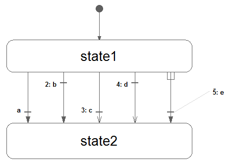
For the 5 transitions above, the settings are as follows, from left to right: immediate = true, false, true, false, true; reset = true, true, false, false, true; synchronize = false, false, false, false, true; priority = 1, 2, 3, 4, 5. The recommended color is {95, 95, 95} for states and for transition text and {175,175,175} for transition lines. ]
The annotation for graphics of transition() has the following structure: annotation(Line(…), Text(…)); and for initialState(): graphical-primitives(Line(…)); with Line and Text annotations defined in chapter 18.
[ Example:
]
The Text annotation representing the transition condition can use the notation %condition to refer to the condition expression.
The extent of the Text is interpreted relative to either the first point of the Line, in the case of immediate=false, or the last point (immediate=true).
In addition to the line defined by the points of the Line annotation, a perpendicular line is used to represent the transition. This line is closer to the first point if immediate=false otherwise closer to the last point.
If the condition text is somewhat distant from the perpendicular line, a dimmed straight line joins the transition text and the perpendicular line [ See the rightmost transition above. ].
If reset=true, a filled arrow head is used otherwise an open arrow head. For synchronize=true, an inverse “fork” symbol is used in the beginning of the arrow [ See the rightmost transition above. ].
The value of the priority attribute is prefixing the condition text followed by a colon if priority > 1.
The initialState line has a filled arrow head and a bullet at the opposite end of the initial state [ as shown above ].
17.3 State Machine Semantics
For the purpose of defining the semantics of state machines, assume that the data of all transitions are stored in an array of records:
The transitions are sorted with lowest priority number last in the array; and the priorities must be unique for each value of “from”. The states are enumerated from 1 and up. The transition conditions are stored in a separate array c[:] since they are time varying.
The semantics model is a discrete-time system with inputs { c[:], active, reset} with t being an array corresponding to the inputs to the transition operator, outputs {activeState, activeReset, activeResetStates[:]} and states {nextState, nextReset, nextResetStates[:]}. For a top level state machine, active is always true. For sub-state machines, active is true only when the parent state is active. For a top level state machine, reset is true at the first activation only. For sub-state machine, reset is propagated from the state machines higher up.
17.3.1 State Activation
The state update starts from nextState, i.e., what has been determined to be the next state at the previous time. selectedState takes into account if a reset of the state machine is to be done.
The integer fired is calculated as the index of the transition to be fired by checking that selectedState is the from-state and the condition is true for an immediate transition or previous(condition) is true for a delayed transition. The max function returns the index of the transition with highest priority or 0.
The start value of c is false. This definition would require that the previous value is recorded for all transitions conditions. Below is described an equivalent semantics which just require to record the value of one integer variable delayed.
The integer immediate is calculated as the index of the immediate transition to potentially be fired by checking that selectedState is the from-state and the condition is true. The max function returns the index of the transition with true condition and highest priority or 0.
In a similar way, the Integer delayed is calculated as the index for a potentially delayed transition, i.e. a transition taking place at the next clock tick. In this case the from-state needs to be equal to nextState:
The transition to be fired is determined as follows, taking into account that a delayed transition might have higher priority than an immediate:
nextState is set to the found transitions to-state:
In order to define synchronize transitions, each state machine must determine which are the final states, i.e. states without from-transitions and to determine if the state machine is in a final state currently:
To enable a synchronize transition, all the stateMachineInFinalState conditions of all state machines within the meta state must be true. An example is given below in the semantic example model.
17.3.2 Reset Handling
A state can be reset for two reasons:
-
•
The whole state machine has been reset from its context.
In this case, all states must be reset, and the initial state becomes active. -
•
A reset transition has been fired.
Then, its target state is reset, but not other states.
The first reset mechanism is handled by the activeResetStates and nextResetStates vectors.
The state machine reset flag is propagated and maintained to each state individually:
until a state is eventually executed, then its corresponding reset condition is set to false:
The second reset mechanism is implemented with the selectedReset and nextReset variables. If no reset transition is fired, the nextReset is set to false for the next cycle.
17.3.3 Activation handling
The execution of a sub-state machine has to be suspended when its enclosing state is not active. This activation flag is given as a Boolean input active. When this flag is true, the sub-state machine maintains its previous state, by guarding the equations of the state variables nextState, nextReset and nextResetStates.
17.3.4 Semantics Summary
The entire semantics model is given below:
17.3.5 Merging Variable Definitions
[ When a state class uses an outer output declaration, the equations have access to the corresponding variable declared inner. Special rules are then needed to maintain the single assignment rule since multiple definitions of such outer variables in different mutually exclusive states needs to be merged. ]
In each state, the outer output variables are solved for and for each such variable a single definition is formed:
last() is special internal semantic operator returning its input. It is just used to mark for the sorting that the incidence of its argument should be ignored. A start value must be given to the variable if not assigned in the initial state.
A new assignment equation is formed which might be merged on higher levels in nested state machines.
17.3.6 Merging Connections to Multiple Outputs
[ Since instances of blocks can be used as states of a state machine it is natural to extend the connection semantics of Modelica to allow several outputs to be connected to one input. ]
It is possible to connect several outputs to an input if all the outputs come from states of the same state machine. In such cases, we get the following constraint equations:
with ui inputs and yi outputs. The semantics is defined as follows. Introduce a variable v representing the signal flow and rewrite the equation above as a set of equations for ui and a set of assignment equations for v:
The merge of the definitions of v is then made according to section 17.3.5: Merging Variable Definitions. The result is after simplification:
17.3.7 Example
[ Consider the following hierarchical state machine:
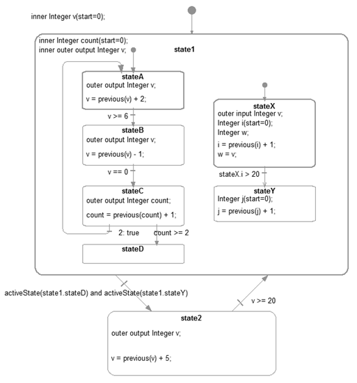
The model demonstrates the following properties:
-
•
state1 is a meta state with two parallel state machines in it.
-
•
stateA declares v as outer output. state1 is on an intermediate level and declares v as inner outer output, i.e. matches lower level outer v by being inner and also matches higher level inner v by being outer. The top level declares v as inner and gives the start value.
-
•
count is defined with a start value in state1. It is reset when a reset transition (v>=20) is made to state1.
-
•
stateX declares the local variable w to be equal to v declared as inner input.
-
•
stateY declares a local counter j. It is reset at start and as a consequence of the reset transition (v>=20) to state1: When the reset transition () fires, then the variables of the active states are reset immediately (so ”count” from state1, and ”i” from stateX). The variables of other states are only reset at the time instants when these states become active. So ”j” in StateY is reset to 0, when the transition stateX.i > 20 fires (after state1 became active again, so after the reset transition ).
-
•
Synchronizing the exit from the two parallel state machines of state1 is done by checking that stated and stateY are active using the activeState function.
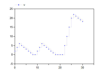
The Modelica code (without annotations) is:
The behavior of the state machine can be seen in the plots of v:
The transition from state1 to state2 could have been done with a synchronize transition with condition=true instead. The semantically equivalent model is shown below: